Chapter 3 DESI MRM
3.1 Introduction
The principle of DESI is simple: a pneumatically assisted electrospray needle produces charged droplets of solvent, which are directed onto the surface to be analyzed. A thin film of solvent is created on a surface, and thus the components located in this area are dissolved. A new portion of charged droplets is responsible for releasing the secondary micro droplets with analytes from the surface. Finally, secondary droplets are evaporated by standard electrospray mechanism on their way to the inlet of the mass spectrometer.
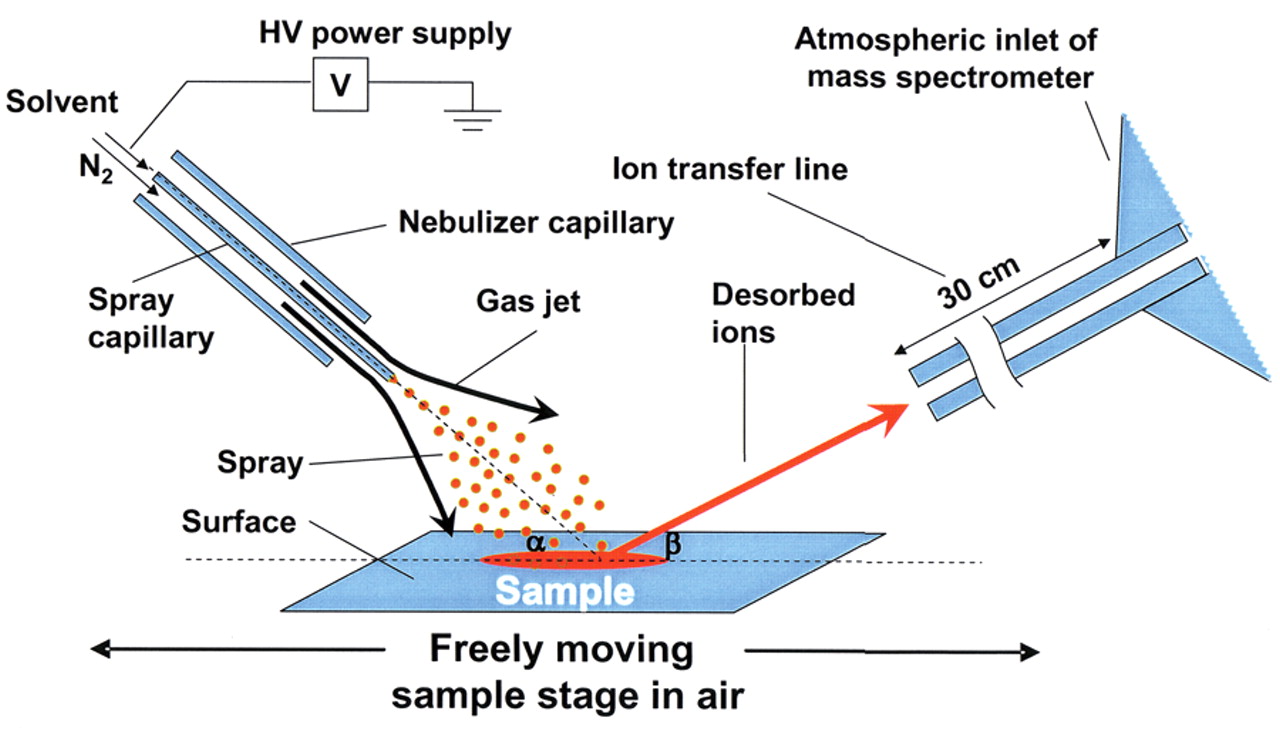
Figure 3.1: DESI ion source
Multiple reaction monitoring (MRM) is the most common method for quantification of analytes by LC/MS/MS. In MRM, ions are selected to make it through the first quadrupole and into the collision cell. These ions are referred to as the precursor, or parent, ion. These ions are fragmented in the collision cell. Certain fragment ions referred to as product, or daughter, ions are selected to make it through the second quadrupole. The transition from precursor/parent ion to product/daughter ions is referred to as an ion transition. For example, the precursor ion (quasimolecular ion) of morphine is 286. The most intense ions created by the fragmentation of 286 is 201, 181, and 165. This gives us three ion transitions for morphine: 286 → 201, 286 → 181, and 286 →165. For analysis, we might want to use 286 → 201 as the quantitative ion transition and 286 → 181 as the qualifier ion transition.
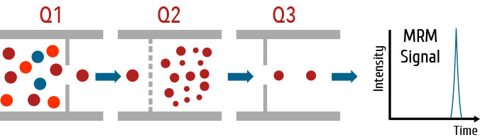
Figure 3.2: Multiple reaction monitoring
3.2 Pratical user manual
3.2.1 Ion Transfer Capillary Installation
Efficient collection of the ions generated in the DESI 2D system requires a close proximity of the ion inlet of the mass spectrometer to the sample being analyzed. Therefore a large diameter, bazooka ion transfer capillary is included with the system to allow for analysis of larger sample areas with Waters mass spectrometers. In addition, the ion transfer capillary is slightly inclined such that there is clearance for samples to pass below the capillary.
Installation steps:
Ensure the instrument has been placed in Standby mode.
With the ionization source removed and the interface cooled to room temperature, close vacuum isolation valve.
Remove the ESI ion sampling cone/cone gas nozzle by rotating the components clockwise to release them from the ion block.
Carefully assemble the bazooka extension by placing the ion sampling cone into the bazooka fitting in the same manner in which it fits the original desolvation gas cone.
Place the o‐ring around the base of the ion sampling cone as shown in Figure 3.3.
Slide the ion transfer capillary assembly into receiving slot on the ion block with the inlet tubing pointing straight upwards. The ion sampling cone will insert into the ion block. This part fits the same manner as the ion sampling cone/cone gas nozzle.
Carefully place the 5 mm wrench provided with the system kit over the wrench flats on the bazooka inlet cone.
Rotate the bazooka inlet counter clockwise (downwards) until the front edge of the bazooka cone is aligned with the front edge of the ion block. The capillary will have a slight (5°) downward slope when installed.
Slowly turn the handle of the vacuum isolation valve to its open position
Return ion block temperature to its normal operating value
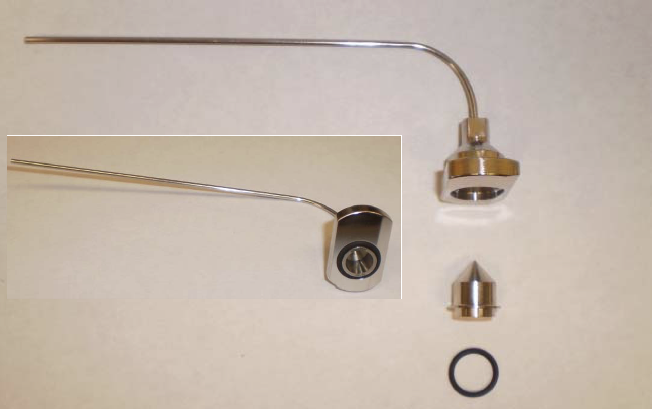
Figure 3.3: Assemble bazooka ion transfer capillary
3.2.2 Setting contact closure for DESI imaging
DESI should be used to trigger the MS acquisition. Below is the contact closure setting.
In masslynx software: Inlet Method –> Tool –> Instrument configuration –> Event & Triggering –> Event in [√] 1 –> Pump: Trigger by Software; Detector: Trigger by contact Closure
3.3 Trouble shooting
3.3.1 DESI stage is not moving (properly)
Description: DESI 2D stage is either not moving or it is not moving properly. For instance, the system cover blocks its movement.
Solution: (1) If the DESI 2D stage does not move at all, make sure that the motor control cable is connected the DESI 2D motion control box and/or the power of the control box is on. (2) If the system cover blocks the DESI 2D stage movement, it means that the sample stage height position is not correct. Adjust it accordingly.
3.3.2 Vacuum lost
Description: The vacuum is lost when we turn on the vacuum isolation valve
Reason: The ESI sampling cone and/or o-ring are not placed in bazooka extension
Solution: Make sure to put sample cone and o-ring in the ESI gas cone. See Section 3.2.1 for details.
3.3.3 DESI source optimization
The following recommended parameters shown in Figure 3.4 can be used as the start for DESI source optimization. We have found that Tip-to-inlet distance is the most critical parameter to enhance ion signal intensity.
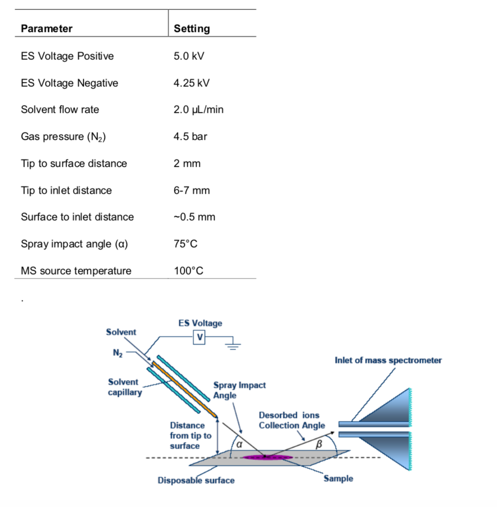
Figure 3.4: Recommended parameters
Red Sharpie marker pen which contains a red dye (Rhodamine 6G C28H31N2O3Cl) and generates an intense ion at _m/z) 443.2335 in positive ion mode, and Black Staedtler Lumocolor fine permanent marker (unknown black dye) which gives an intense signal at m/z 666.06 in negative ion mode are usually used for DESI parameter optimization in our lab.
The solvent, 98:2 methanol: water + 0.01% formic acid is introduced at a flow rate of 2 μL/min. Omni Slides (76 x 26mm microscope slides with hydrophobic array substrates) which have 24 discrete sample spotting locations, with a 3 mm diameter, are used to introduce the samples. Mark the center of the spots (furthest spot to the left) using the red Sharpie for positive ion and the black Staedtler Lumocolor for negative ion.