Chapter 2 MALDI2-Orbitrap
2.1 Introduction
The sensitivity of MALDI is restricted mainly by two factors: (1) low ionization efficiency. Less than 1 out of 1000 desorbed molecules is on average ionized; and (2) strong ion suppression effects, particular in positive ion mode. A laser-based post-ionization (PI) approach is introduced to overcome these limitations (Soltwisch et al. 2015). Using this technique, named MALDI-2, the plume of the matrix and analyte molecules generated by the standard MALDI laser is intercepted by a second PI laser beam. The initiation of secondary MALDI-like ionization processes was found to enable up to 2 orders of magnitude higher sensitivity for numerous classes of molecules (e.g., many lipids, vitamins, and oligosaccharides) in both positive and negative ion modes. The success of the PI approach is found to depend critically on two factors: (1) the confinement of the plume in a buffer gas of several mbars and (2) the use of a PI laser wavelength below the two-photon ionization threshold of the MALDI matrix.
2.1.1 The Instrument
Below is a short description of our MALDI2-Orbitrap instrument.
Ion source: MALDI2 from Spectroglyph
MS: Orbitrap Q-Exactive plus from Thermo
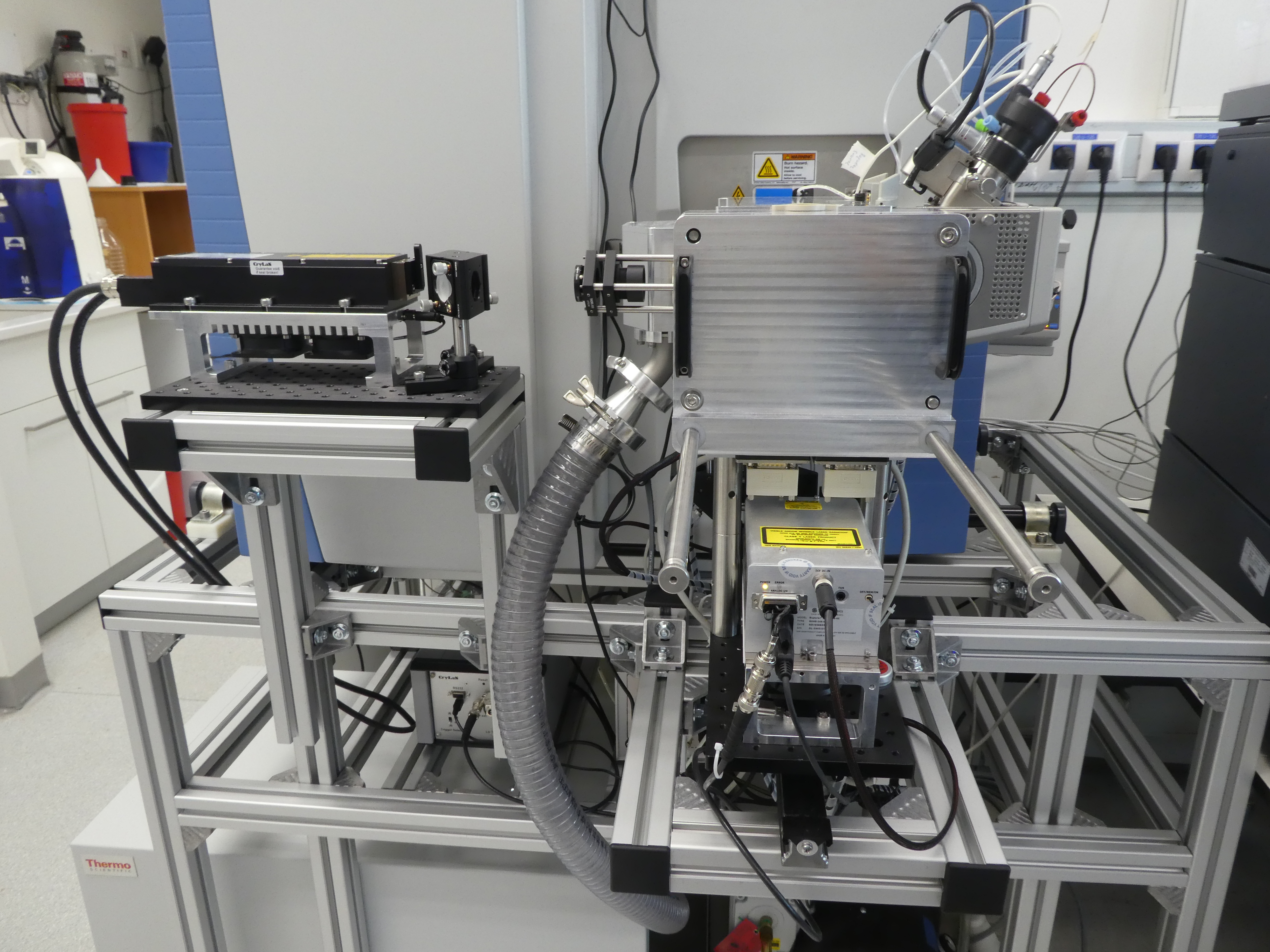
Figure 2.1: MALDI2 source in details
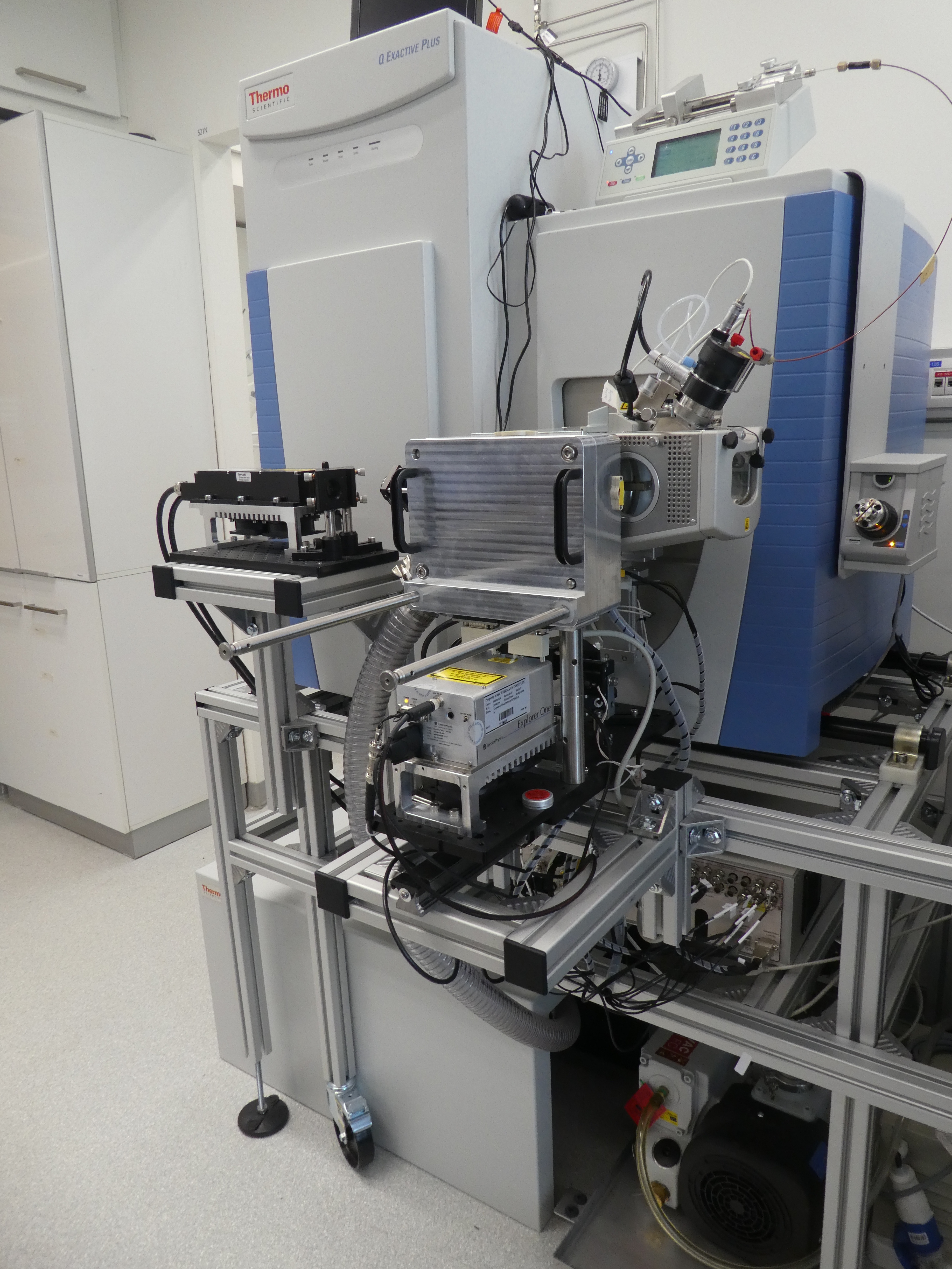
Figure 2.2: MALDI2-Orbitrap-Q-Exactive
2.2 Pratical User manual
The practical user manual here refers to the guides or tutorials which do not appear in the official user manual.
We do not have any official user manual for MALDI2, I have therefore indluded many figures in this section.
As the MALDI2 software, namely MALDI Injector, keeps get updated. Some information below may have been outdated. If you have any daubts, please contact the engineer directly.
2.2.1 MALDI2 Imaging Workflow
2.2.1.1 The sequential steps to load or remove the glass slide from MALDI source
- Disable System
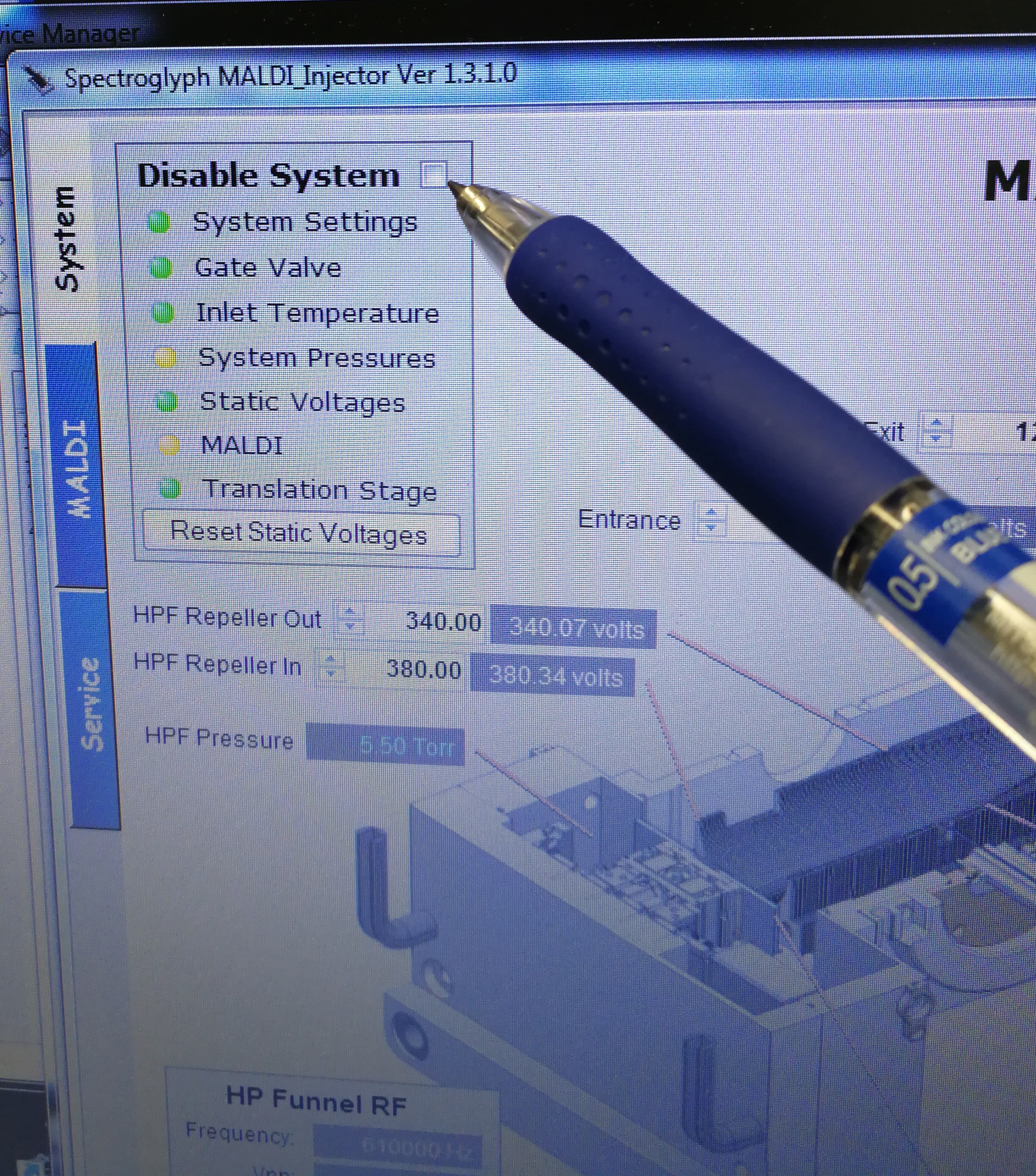
Figure 2.3: Disable system
- Close gate valve and look at end switch status. Make sure that Orbitrap fore vacuum pressure warning pops up.
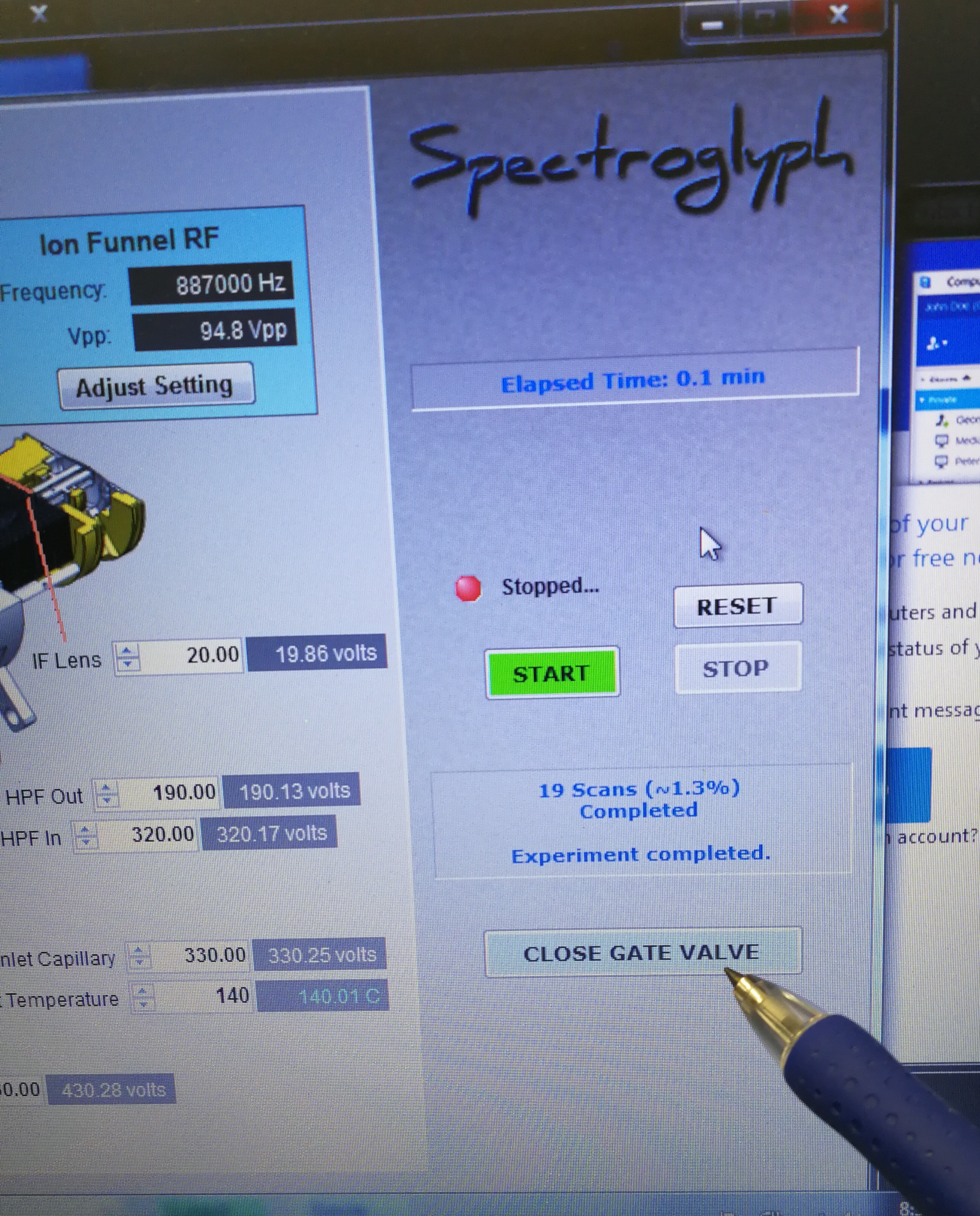
Figure 2.4: Close gate valve
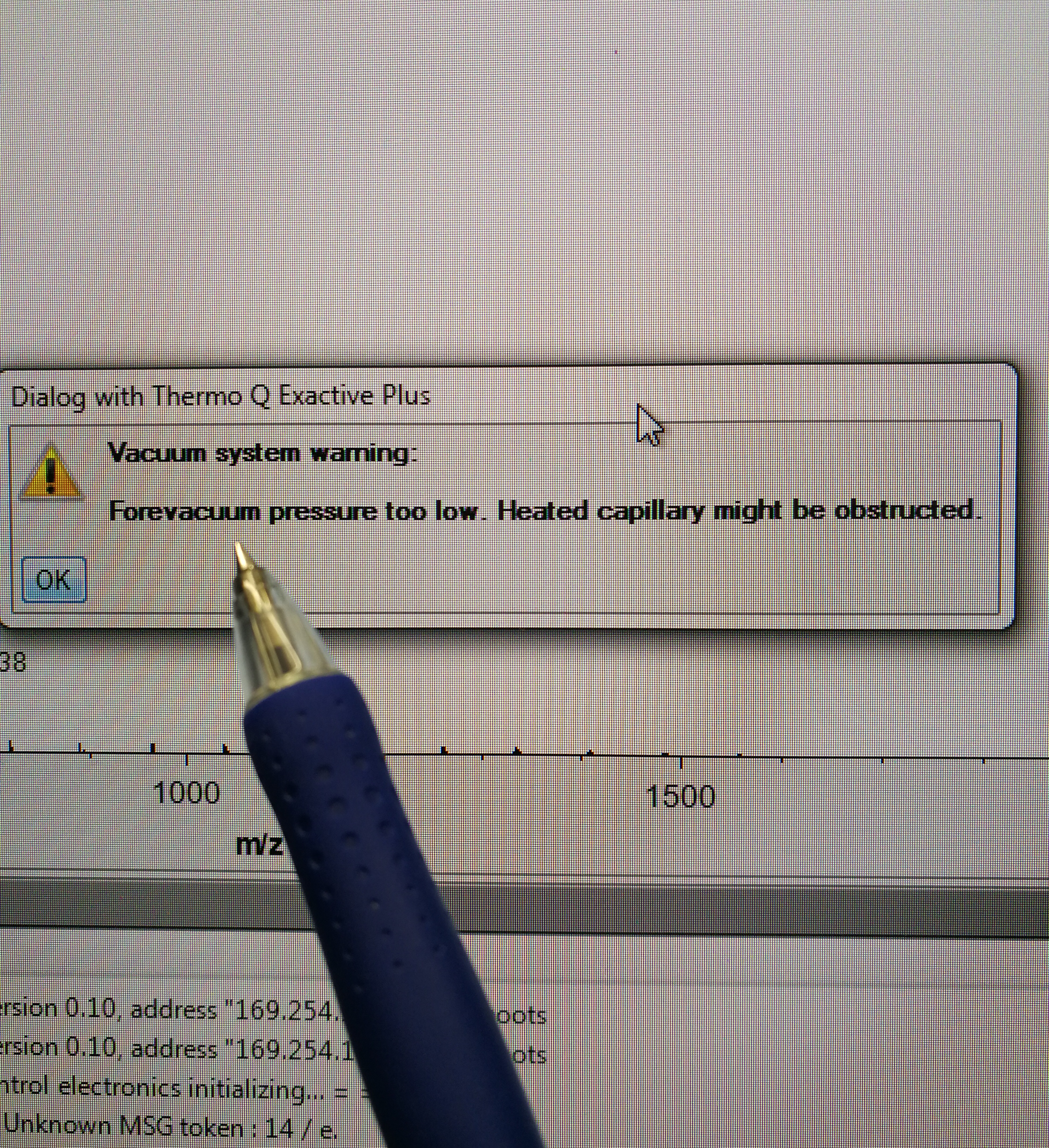
Figure 2.5: Check fore vacuum pressure, and it should show an error like in the figure
Stop the Leybold pump
Pull out the cap and vent the front end

Figure 2.6: pull out the cap
- Open the MALDI source to load or remove the glass slide
2.2.1.2 Set up MALDI imaging sequence for batch mode
- Select the scan areas
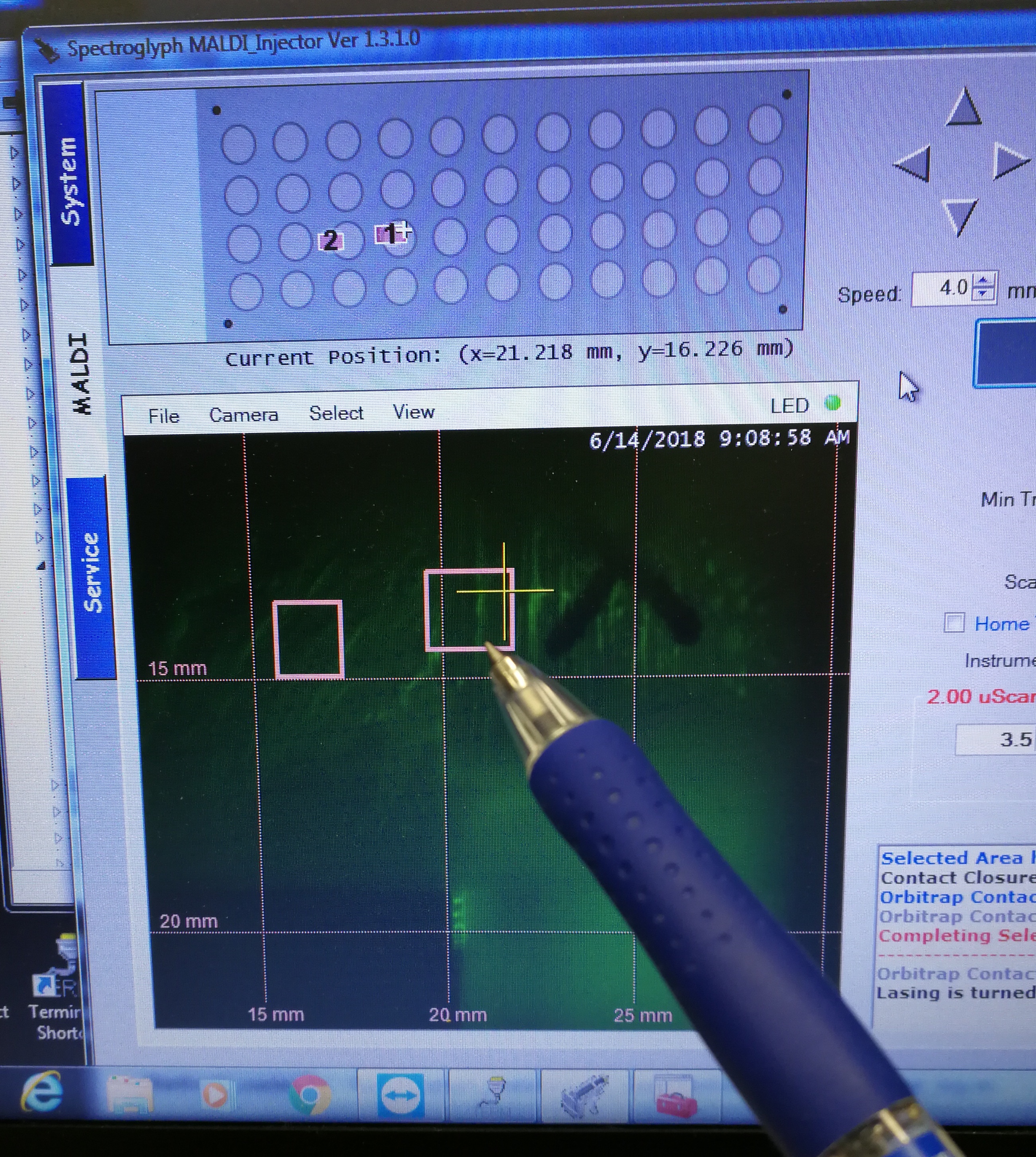
Figure 2.7: select the scan areas
- Go to Sequence Scheduler, add sample names, MALDI method, spatial resolution and (most importantly) pay attention to the Approx time for each sample.
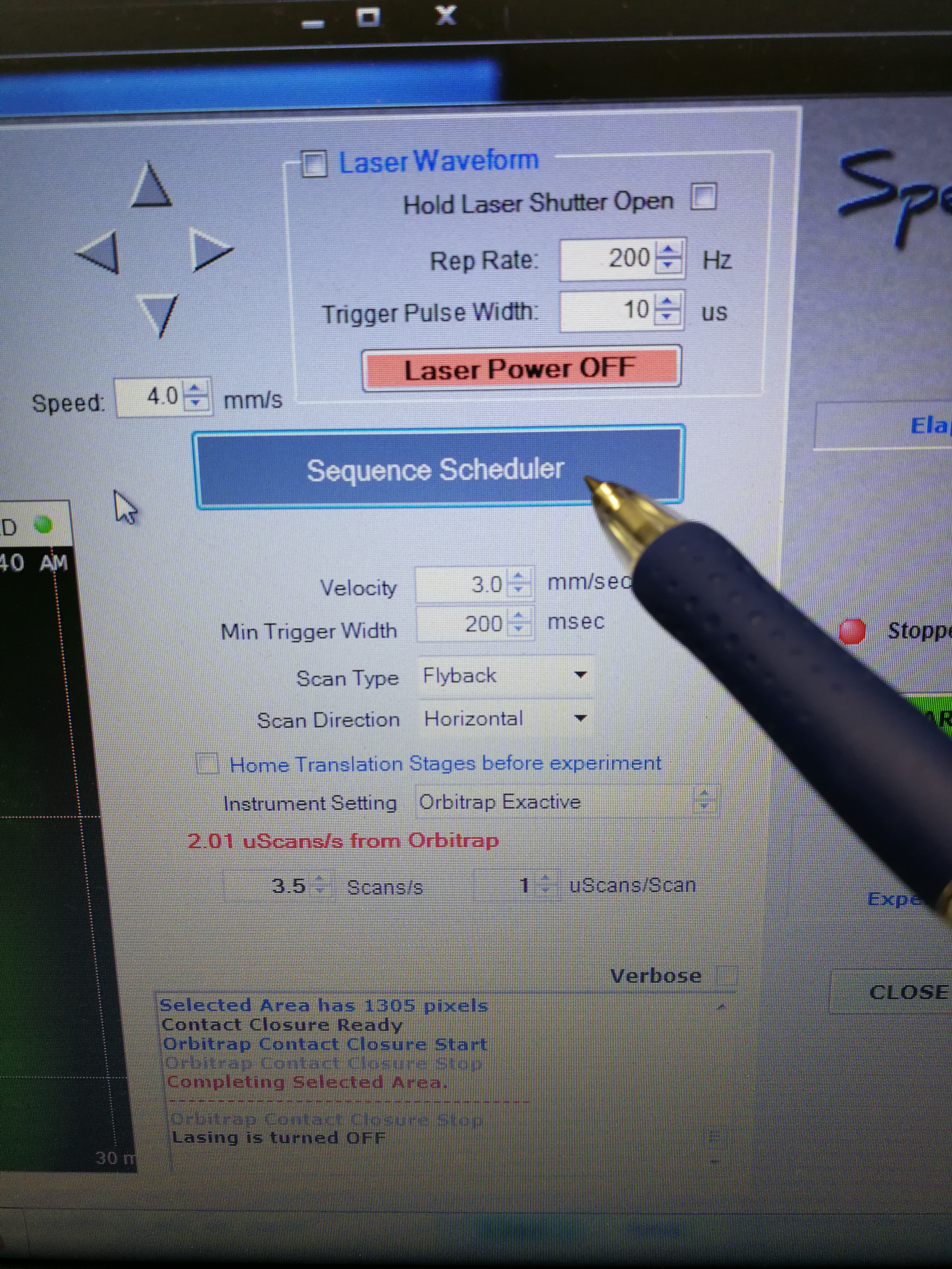
Figure 2.8: sequence scheduler
- Go to Xcalibur – Instrument Setup to set tune file. Open an existing tune file. Then edit the Method duration time and Runtime, they should be the same (pay attention to the format), and a bit longer than the Approx Time calculated in Sequence Scheduler. Note that this tune file should be prepared for each scanning sample (area) as the Approx Time may be different for each scanning sample. Save the tune file.
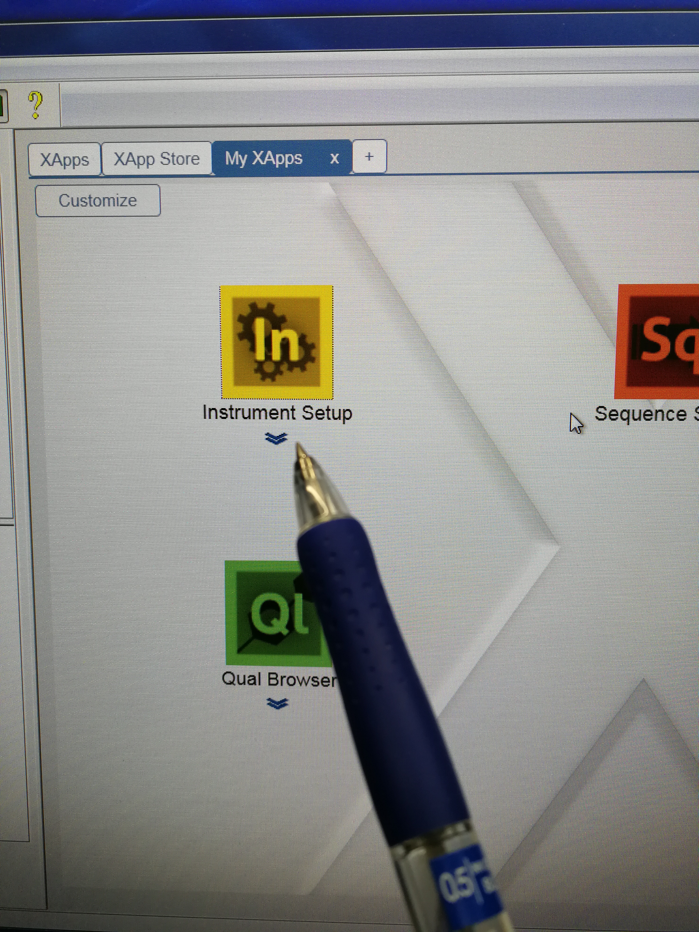
Figure 2.9: Instrument setup page
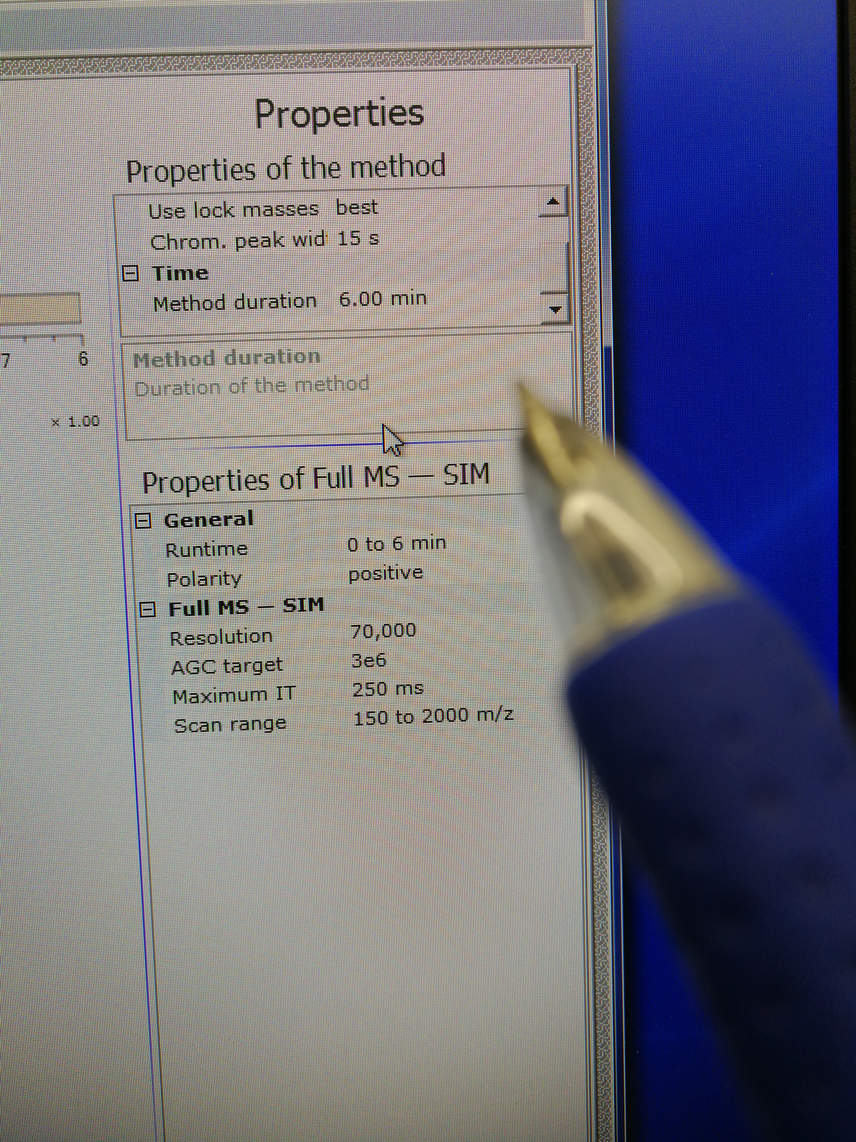
Figure 2.10: set up tune method
- Go to Xcalibur – Sequence Setup. Fill File name, select path and Ins Meth (This is the tune file we just prepared in step 3)
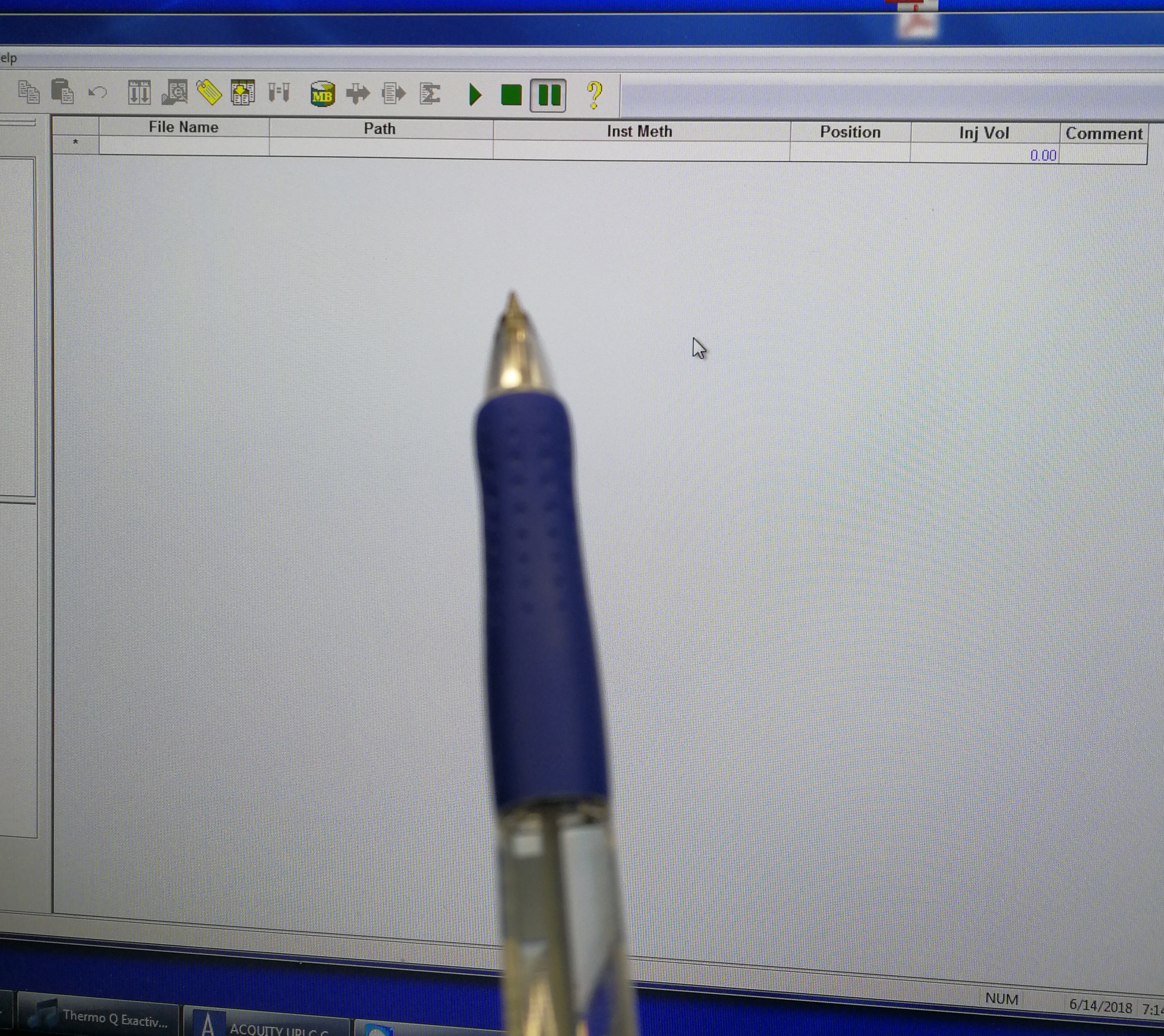
Figure 2.11: set up tune method
- When sequence is setup, go to Xcalibur – Acquisition –On start, select “waiting for contact closure”.
- Start the sequence by select the sequences and click Run Sequence button. Make sure only Orbitrap Instrument is selected. Now you can click start MALDI laser.
2.2.1.3 Optimization of Orbitrap method
In order to enhance the detection of molecules in low mass range, we need to change the drive parameters in ion funnel. The default drive parameter is 30%, it can be reduced to 10% for the detecting of small m/z values, i.e., m/z 74.09.
Additionally, we can also reduce Entrance parameter, from default value 150 to 120.
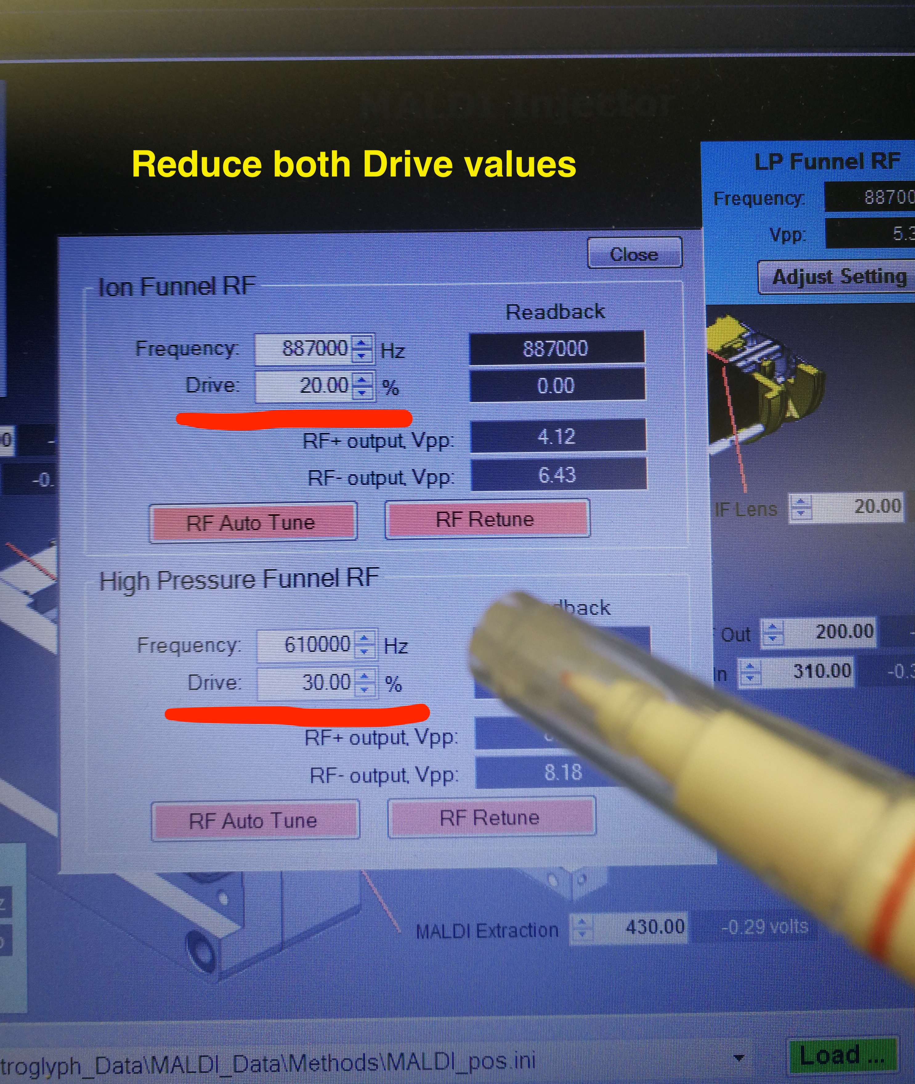
Figure 2.12: Ion Funnel
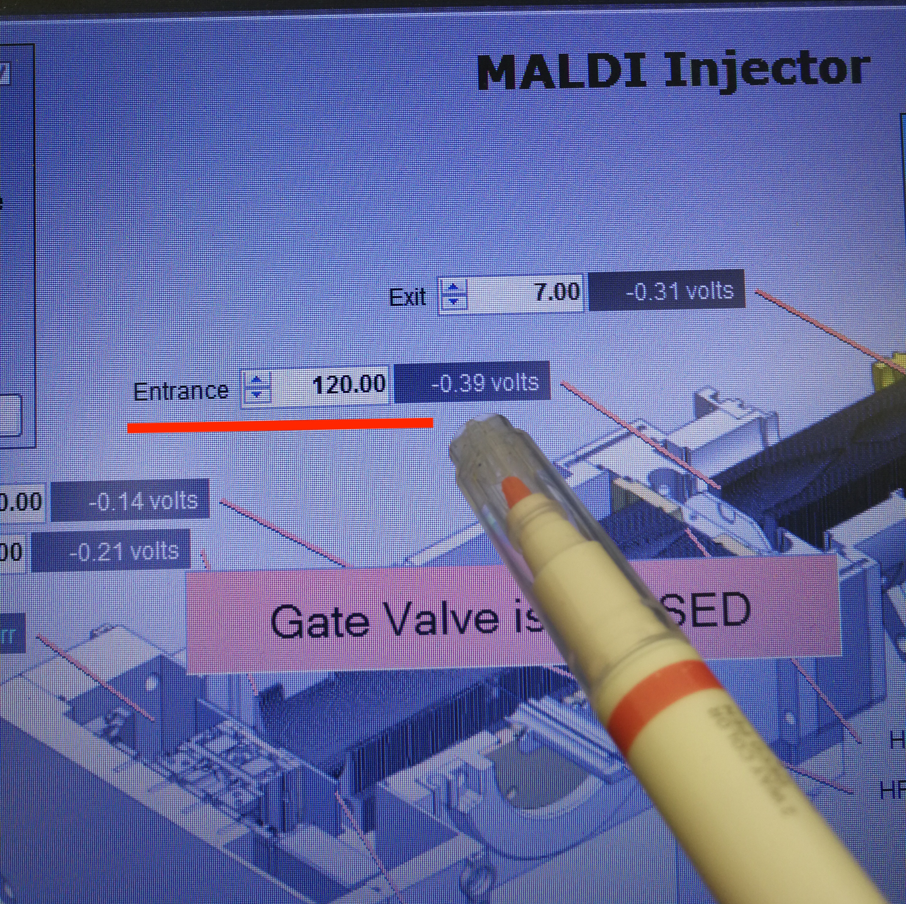
Figure 2.13: Entrance
2.3 Touble shooting
2.3.1 Cannot turn on Explore one laser
- Make sure that the power switch on the laser head is ON position
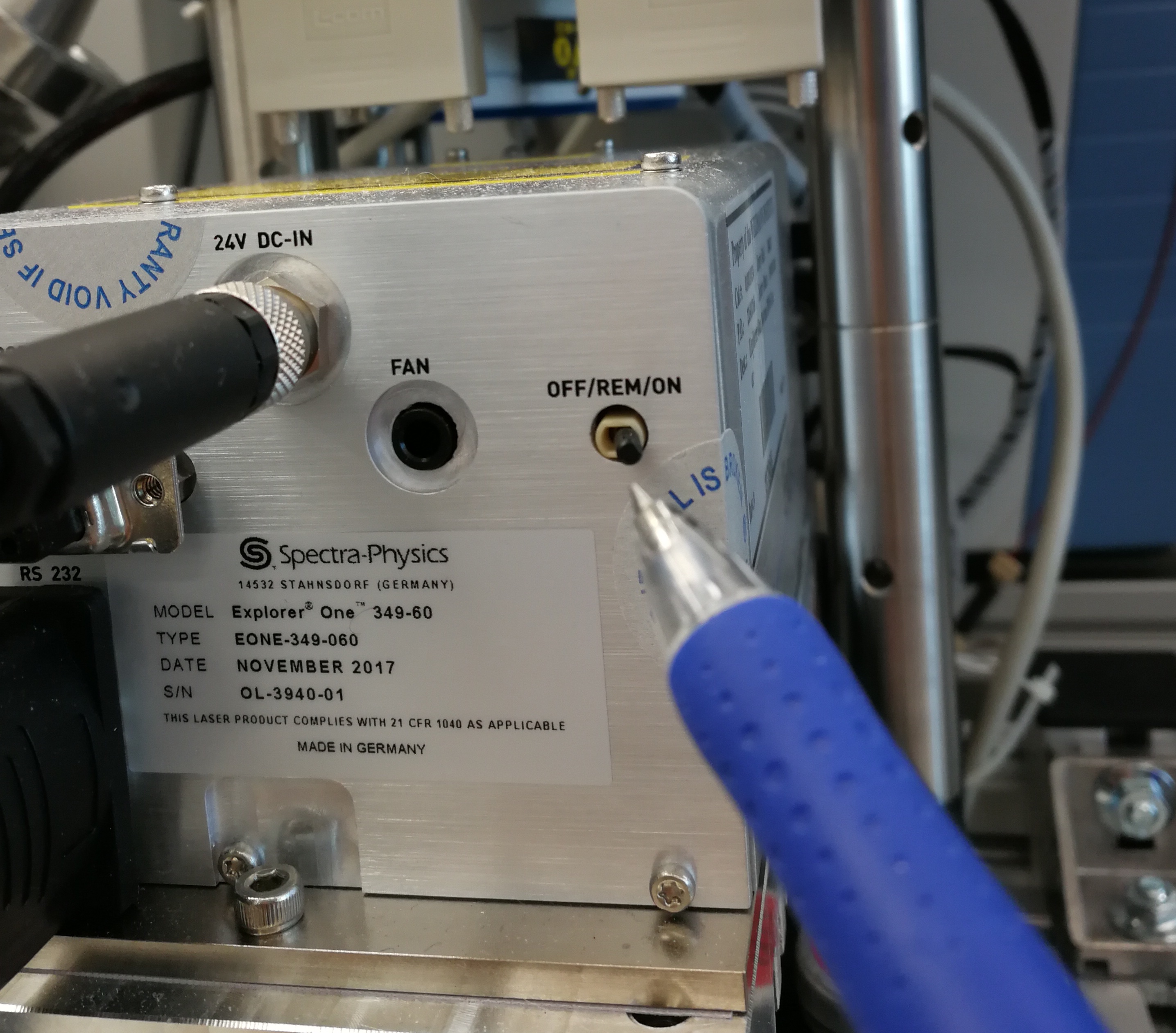
Figure 2.14: power switch is on
- Make sure the COM port matches correctly in Laser Control
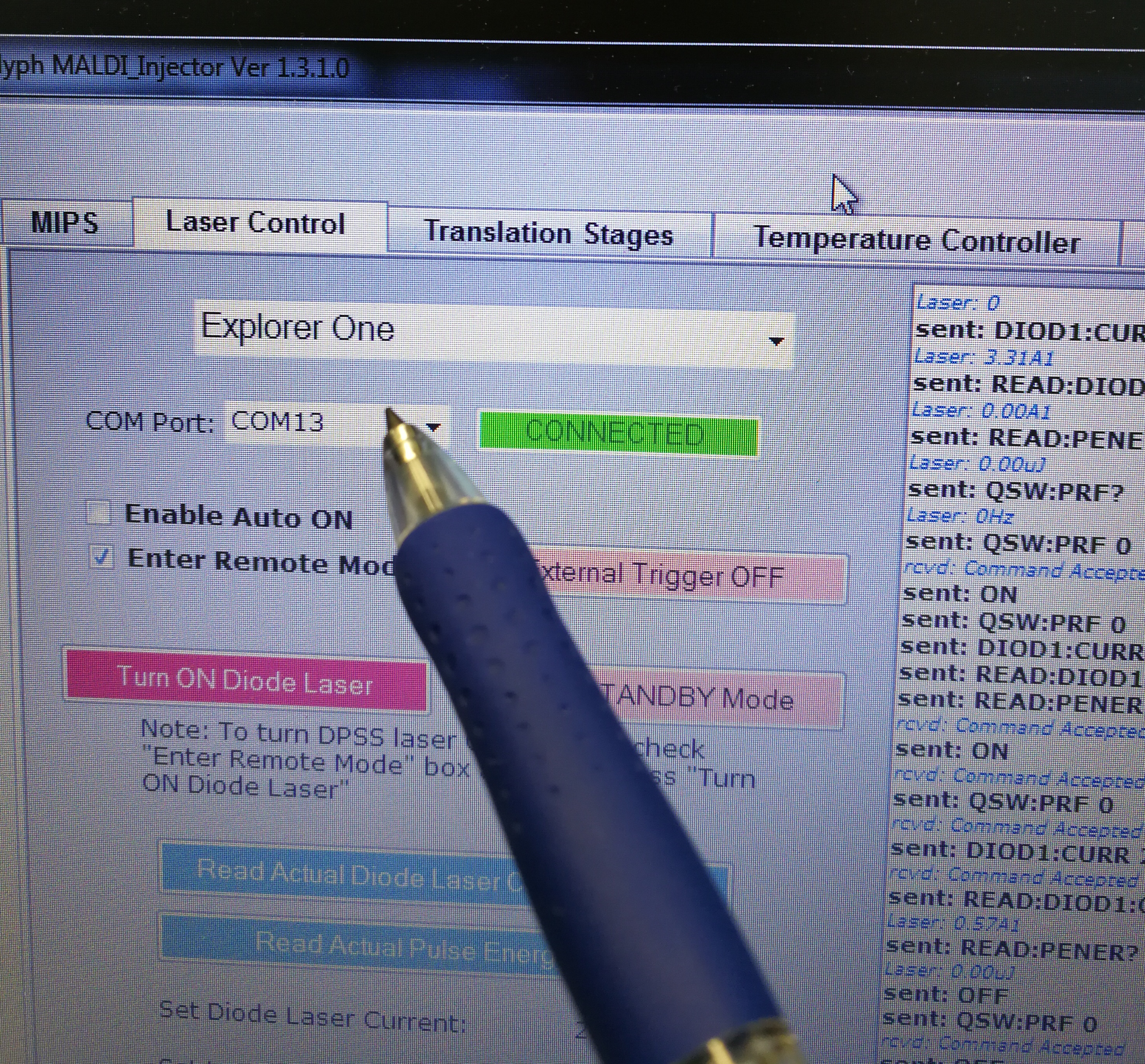
Figure 2.15: COM port
To check the right COM port, go to computer ‘Start’–‘Device Manager’ – ‘Ports (COM & LTP)’. The right port for Explorer One laser is ‘Prolific USB-to-Serial Comm Port (COM13)’
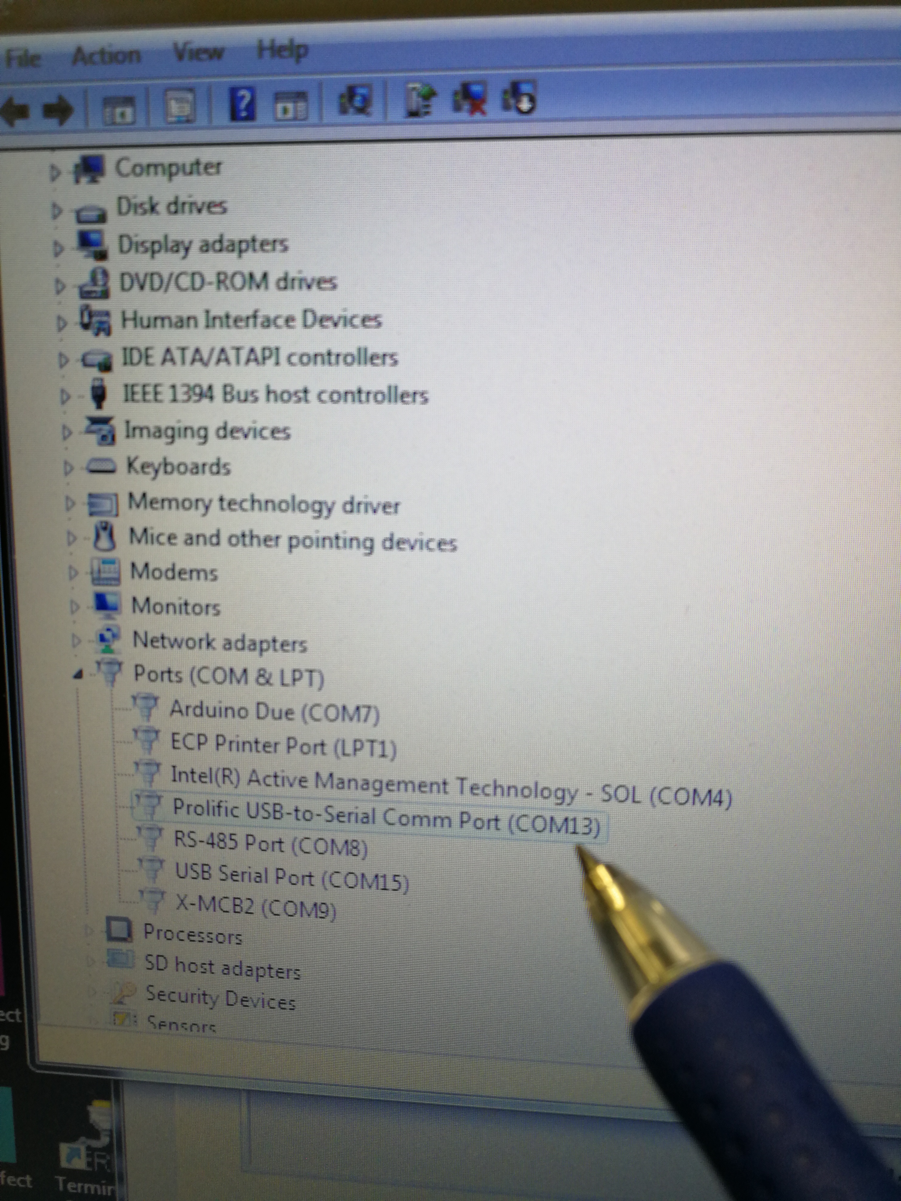
Figure 2.16: Look for the correct COM port
2.3.2 Ion intensity is too low
Description: Ion intensities for both MALDI and MALDI2 are low, and the AGC target for Calmix pos only reach 10% under ESI.
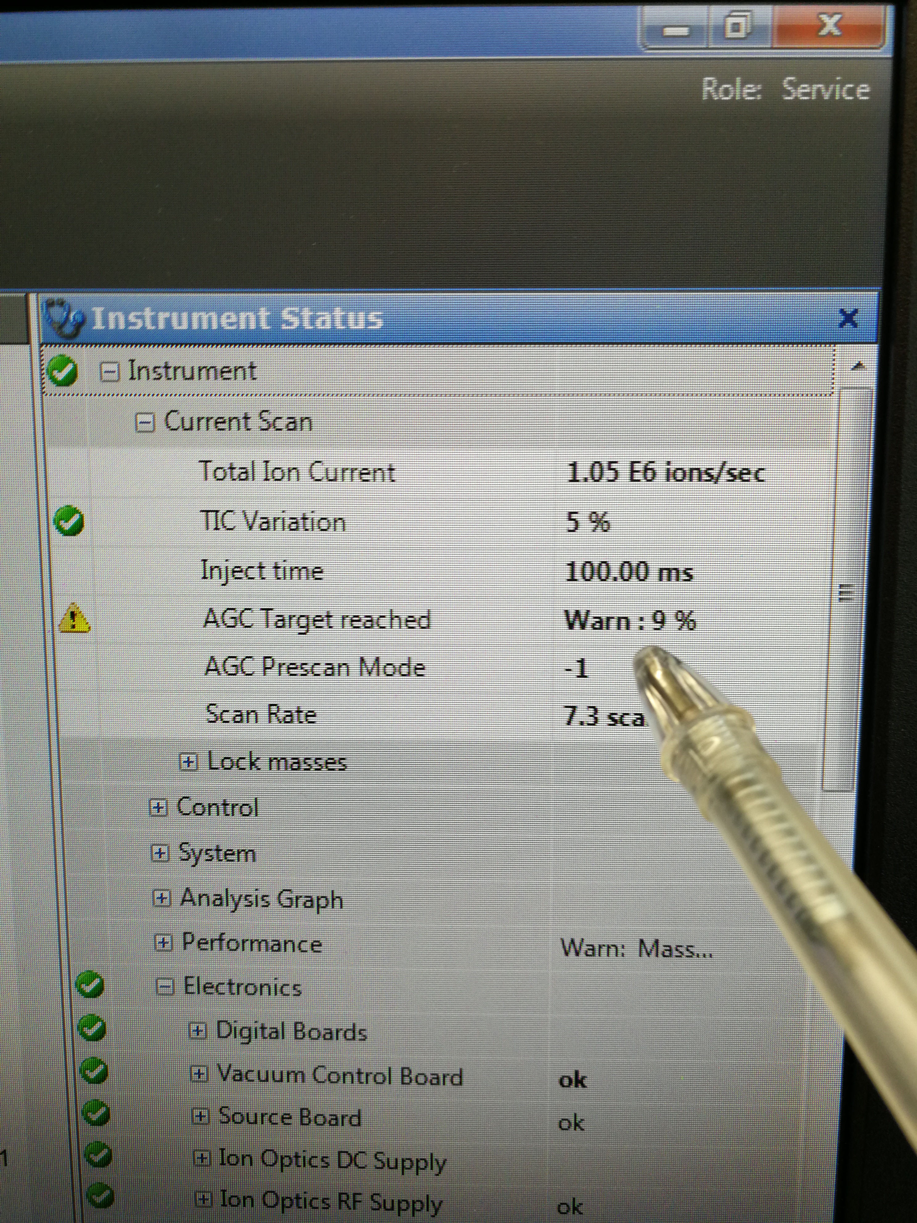
Figure 2.17: AGC taraget reached only 10%
Reason: there is no RF on the funnels.
Solution: reset the firmware
2.3.3 Not all samples are analysed in batch mode
Reason: because the boundary is not correct
Solution: home and center the camera
2.3.4 CryLas laser is not working
Description: As seen in Figure 2.18, there is no laser spot on a piece of white paper.
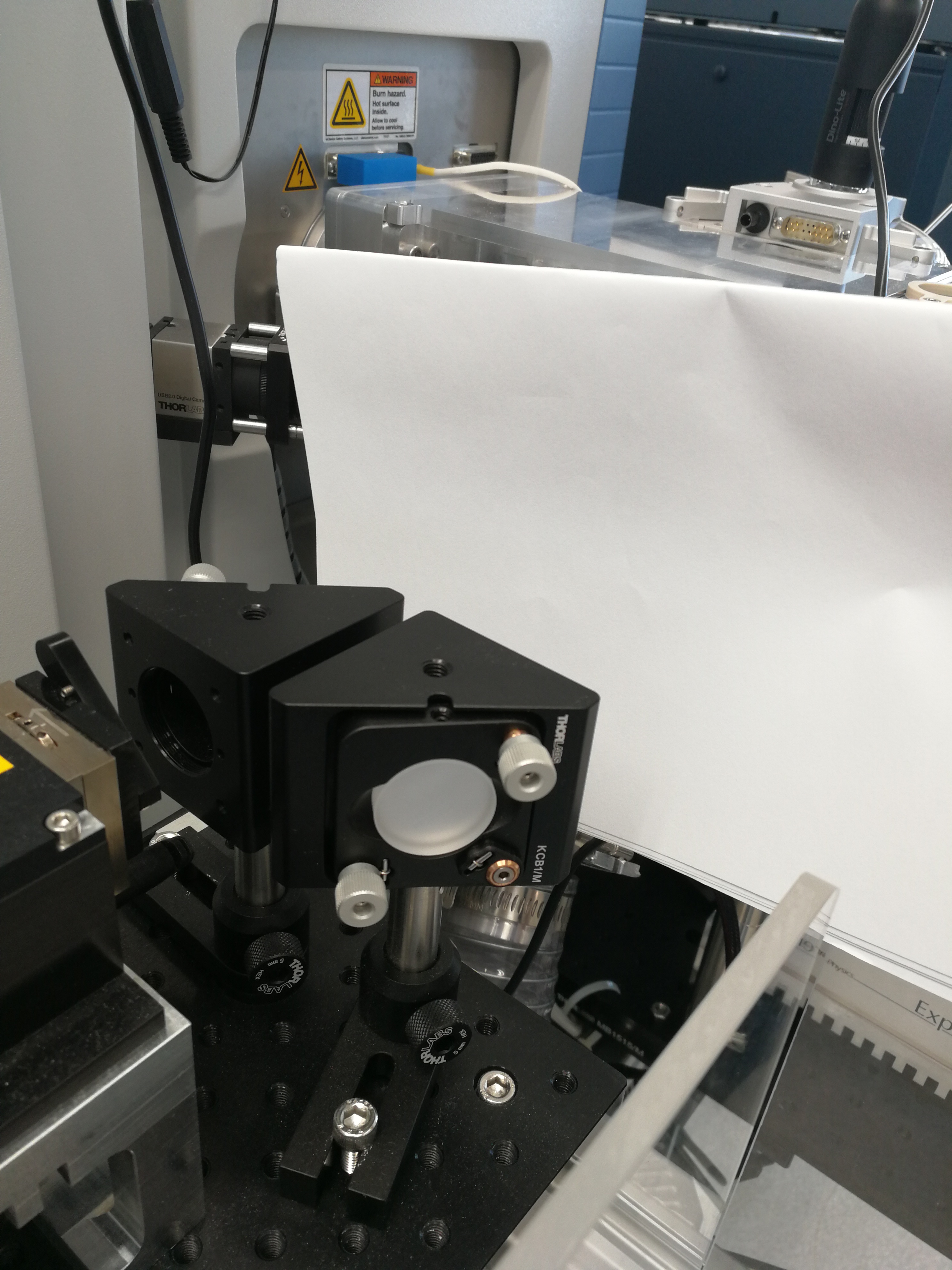
Figure 2.18: No laser spot on a piece of paper
Solution:
- Make sure that the external trigger button is selected.
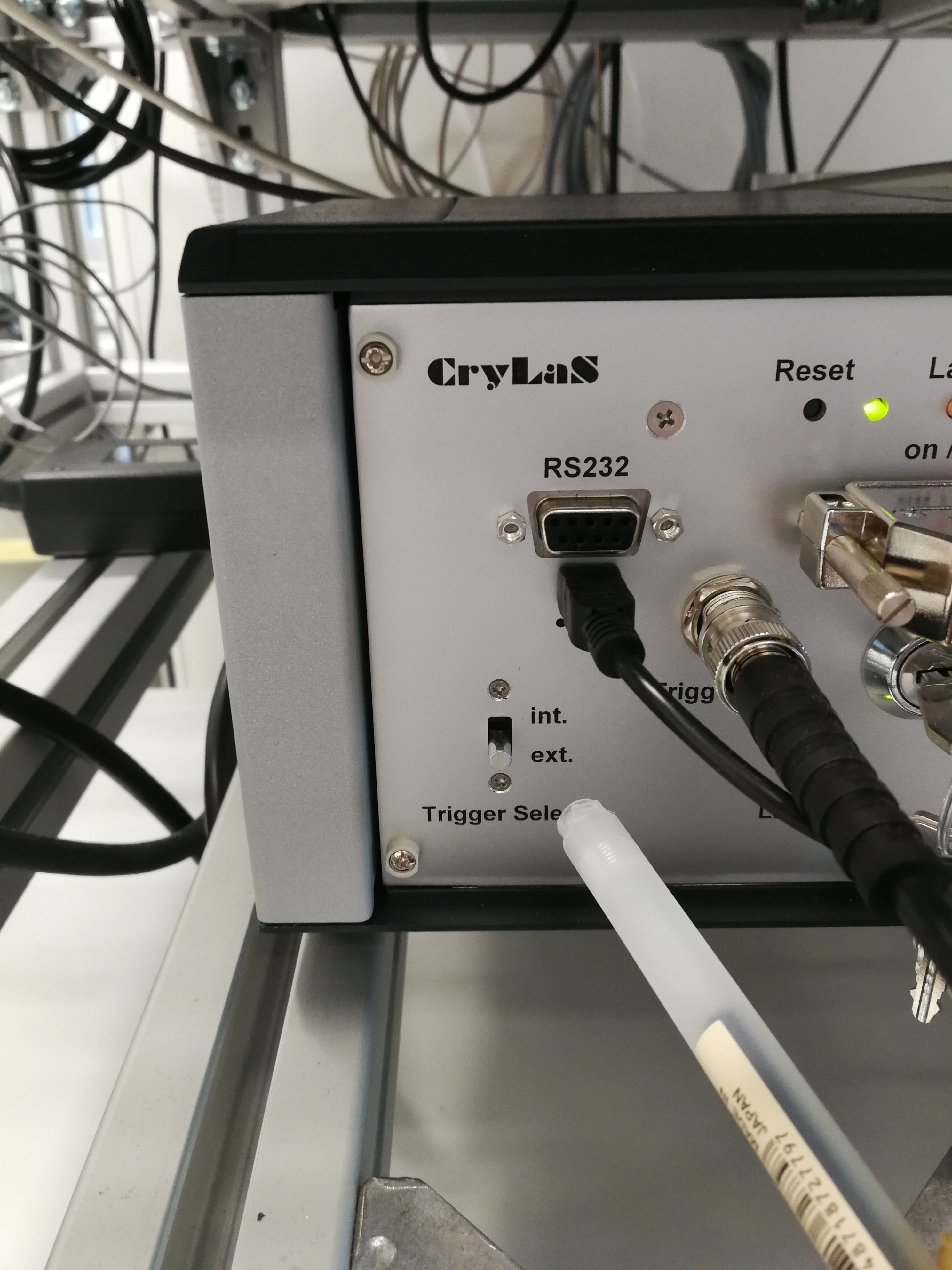
Figure 2.19: External trigger on hard ware
- Make sure that external trigger is also enabled on MALDI injector software
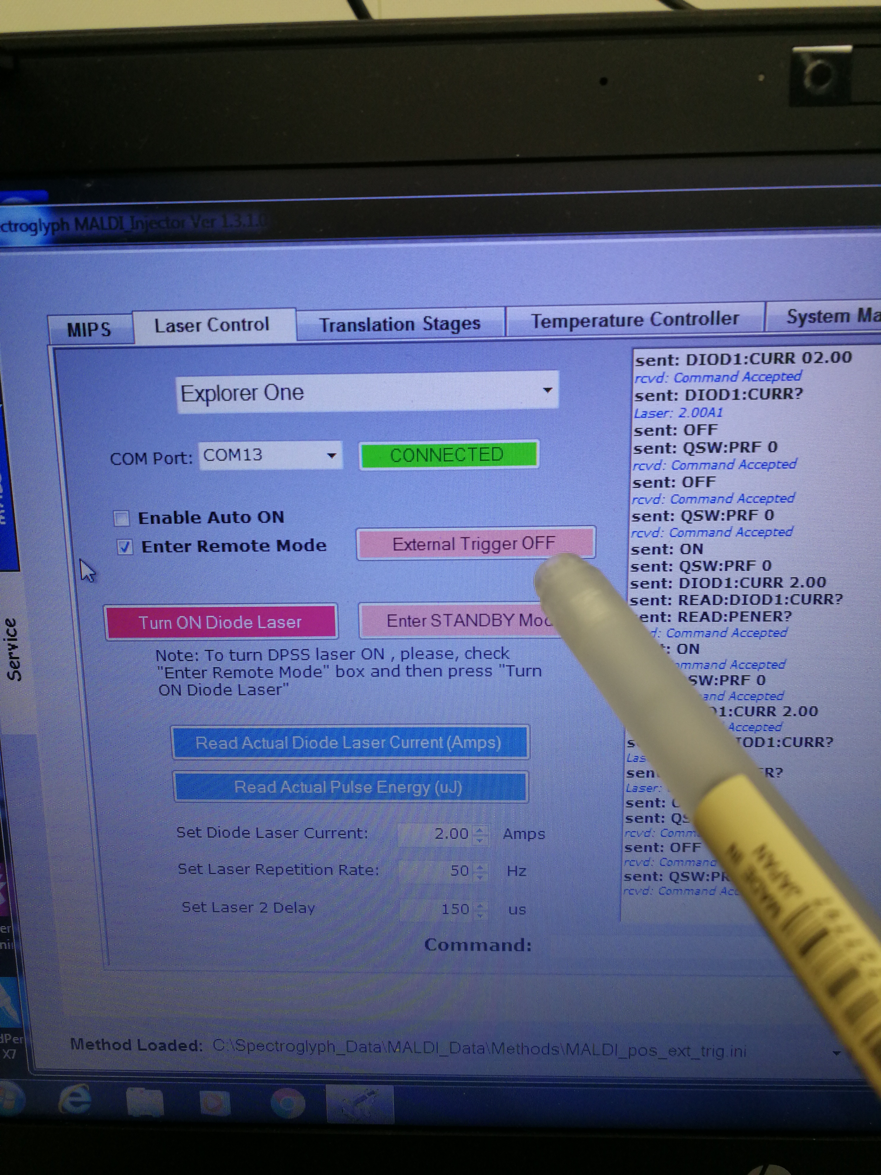
Figure 2.20: External trigger on MALDI injector software
2.3.5 Crylas laser does not generate any extra ions in MALDI2
Reasons: It basically means only Explorer laser works (MALDI only). The most important reason is that CryLas laser does not pass the ion plume, therefore it does not do any contribution to ionization (CryLas laser is not well aligned).
The second possible reason is that the Crylas laser power is not reached. The set value should be 200 uJ, you won’t see any MALDI2 signal below 150 uJ. The NLO temp is the temperature of the internal non linear crystal generating the 266 nm emission. The crystal is very temperature sensitive. The optimum temperature can change over time due to aging of the crystal.
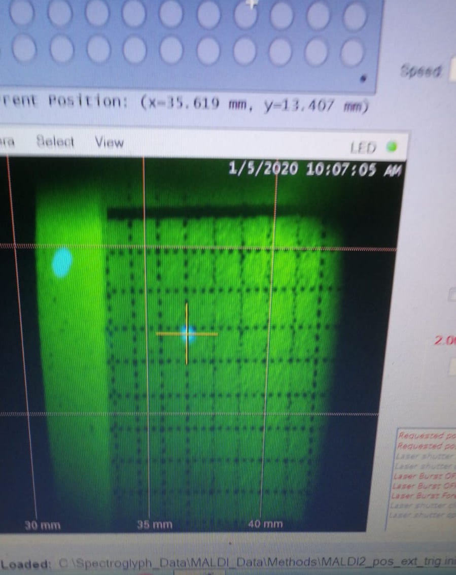
Figure 2.21: An example of Crylas laser shift. The two lasers are not alighed.
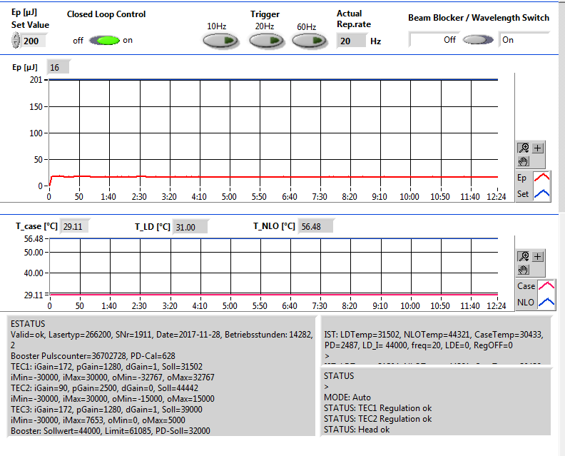
Figure 2.22: An example of low Crylas laser emergy. It has only 16 uJ laser power
Solution:
- You need to align CryLas laser
or (2) The optimum temperature for the crystal should be adjusted. The can be done either by Mikhail or Crylas engineer, e.g., Steffen Prein
Steps:
Here is an official manual for Crylas laser adjustment.
Below is my practical user manual for Crylas laser adjustment.
Prepare the grid paper, and attach it on the glass slide as shown in the figure below. This grid paper will be used to accurately position and align the two lasers.
Load the sample in MALDI2 chamber (sequential of loading the sample is very important, see section 2.2.1.1for details)
When adjusting the laser, you don’t need to start the forevacuum pump, as you need to open the MALDI2 chamber from time to time.
You need to adjust CryLas laser mount 1 and mount 2 to align the CryLas laser. Usually you need try to bring the beam as up as possible with mount 1(1), and then lower it with mount 2 (1). Sometimes, when you bring up/down the beam, the beam will disappear, so you need to bring the beam left/right using mount 1(2) and mount 2(2). See Figure below.
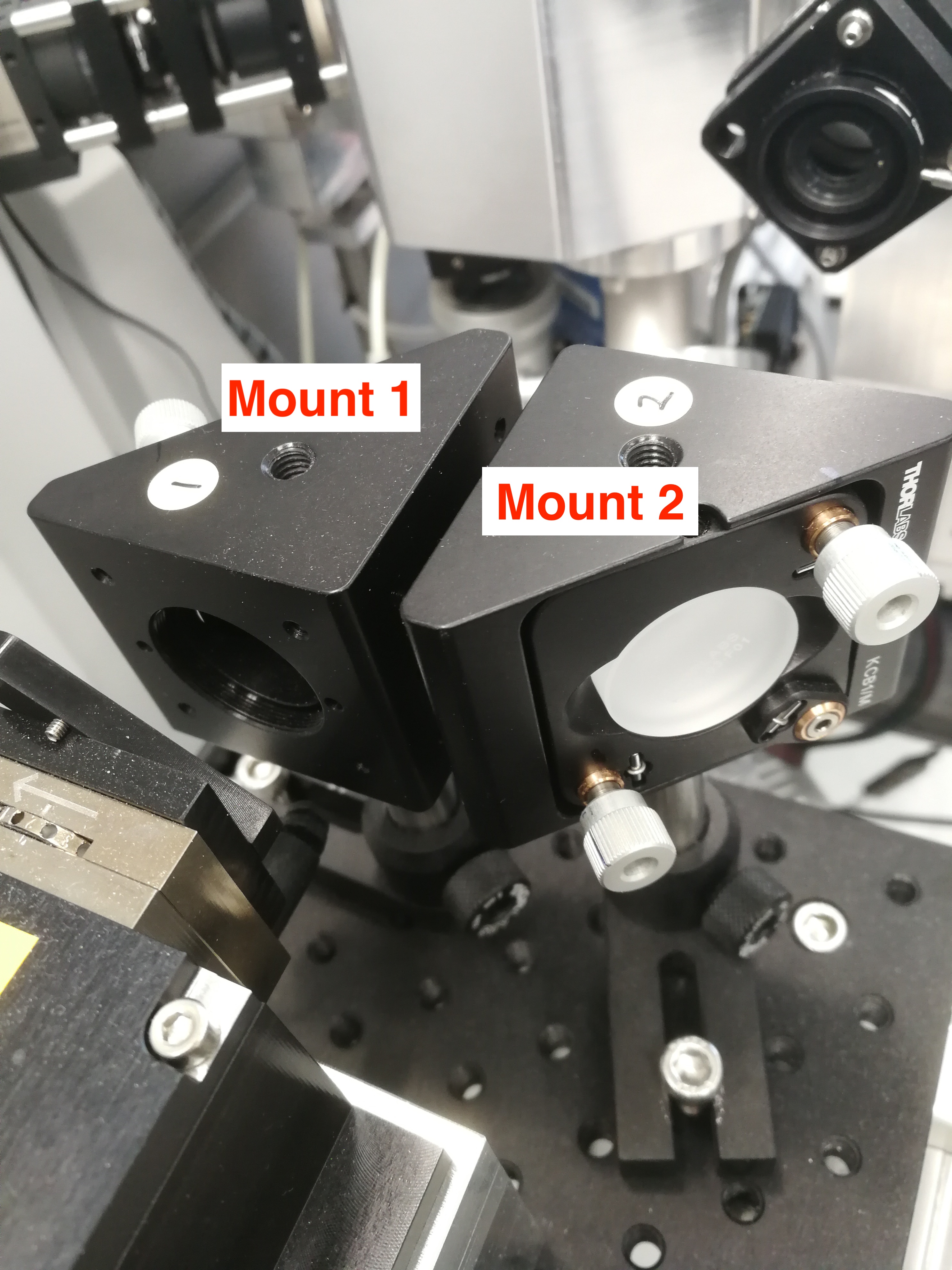
Figure 2.23: CryLas Laser Mount 1 and Mount 2.
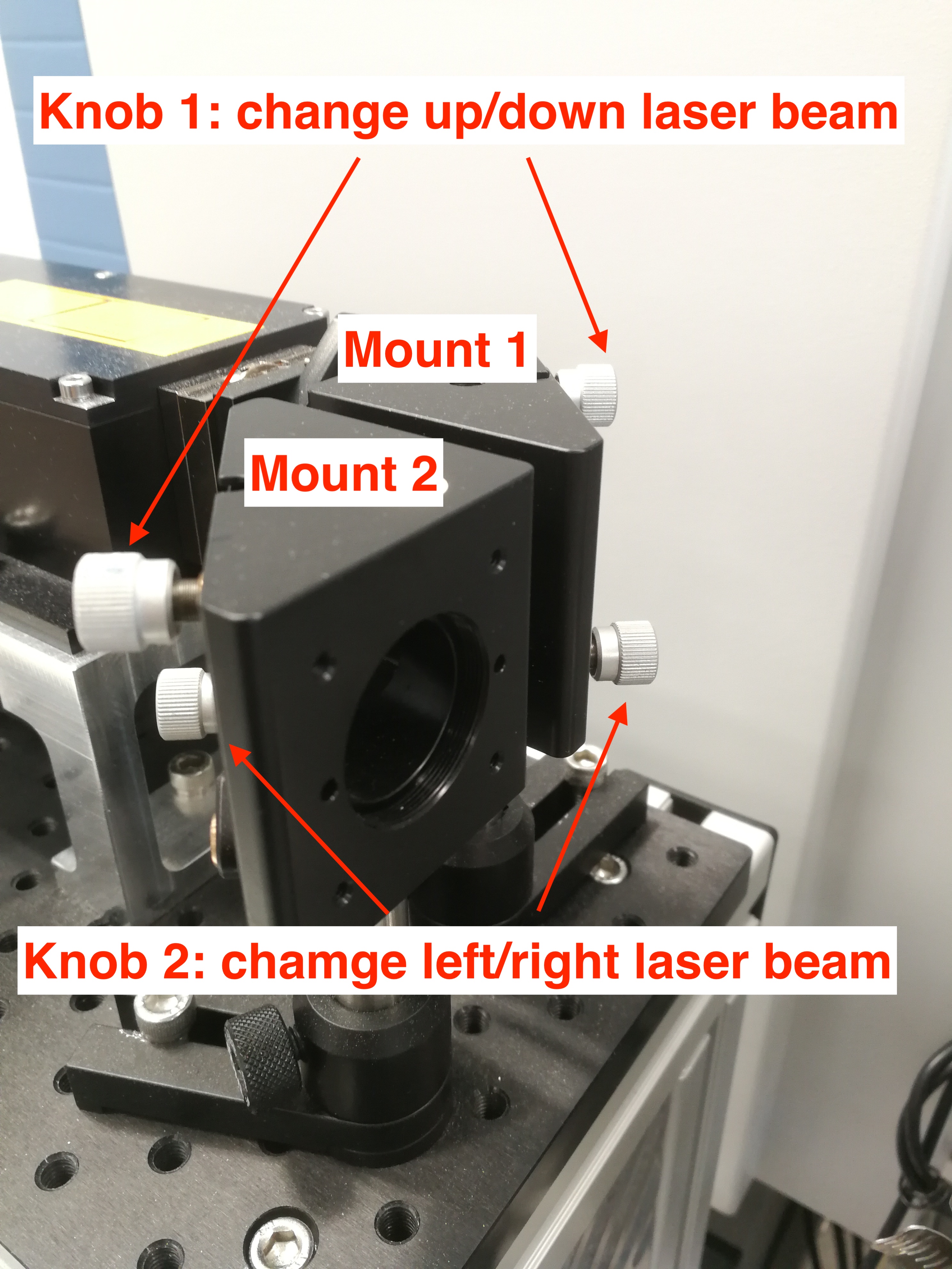
Figure 2.24: CryLas Laser Mount Knobs.
- Meanwhile, you also need to clip the Iris or the entrance window to focus CryLas laser. The CryLas laser should be bright.
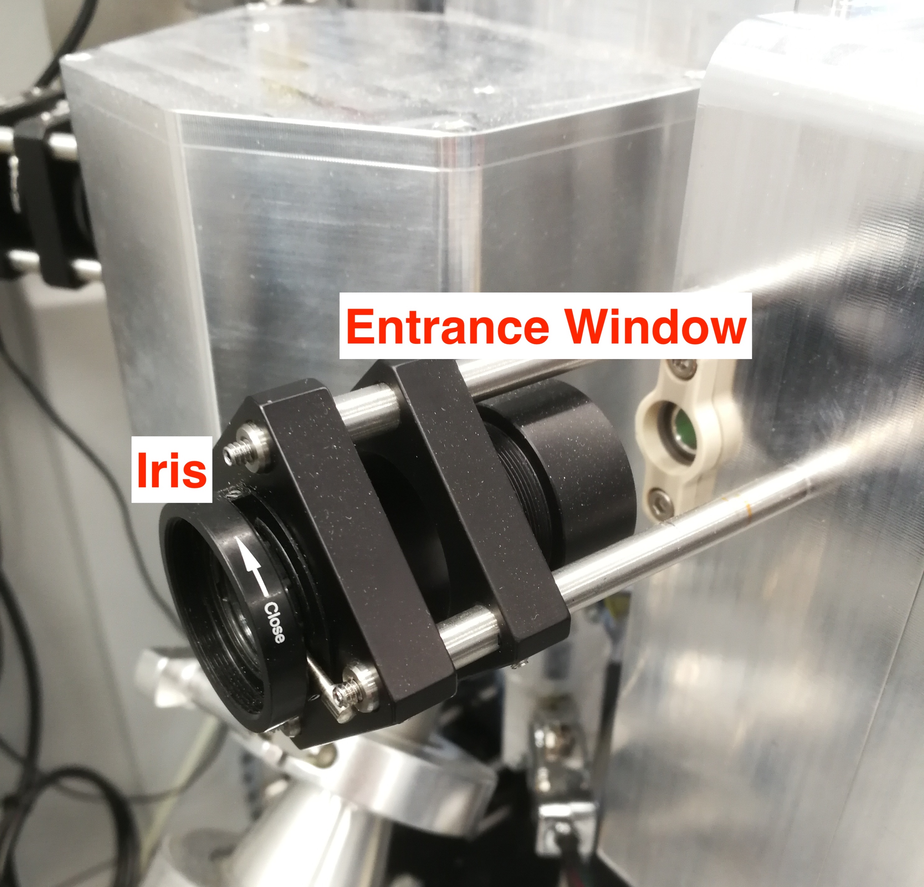
Figure 2.25: Iris and Entrance Window.
When the lasers are aligned, they look like in the figure below. (1. The distance between Crylas and Explorer one laser should be around 0.5 mm; (2) When you open the Crylas laser lid, the Crylas and Explorer spots must overlap on the paper, and the in the place of overlap, the Crylas must be in focus)
After adjusting the laser position, we also need to adjust laser energy. The CryLas laser energy should be around 200 uJ.
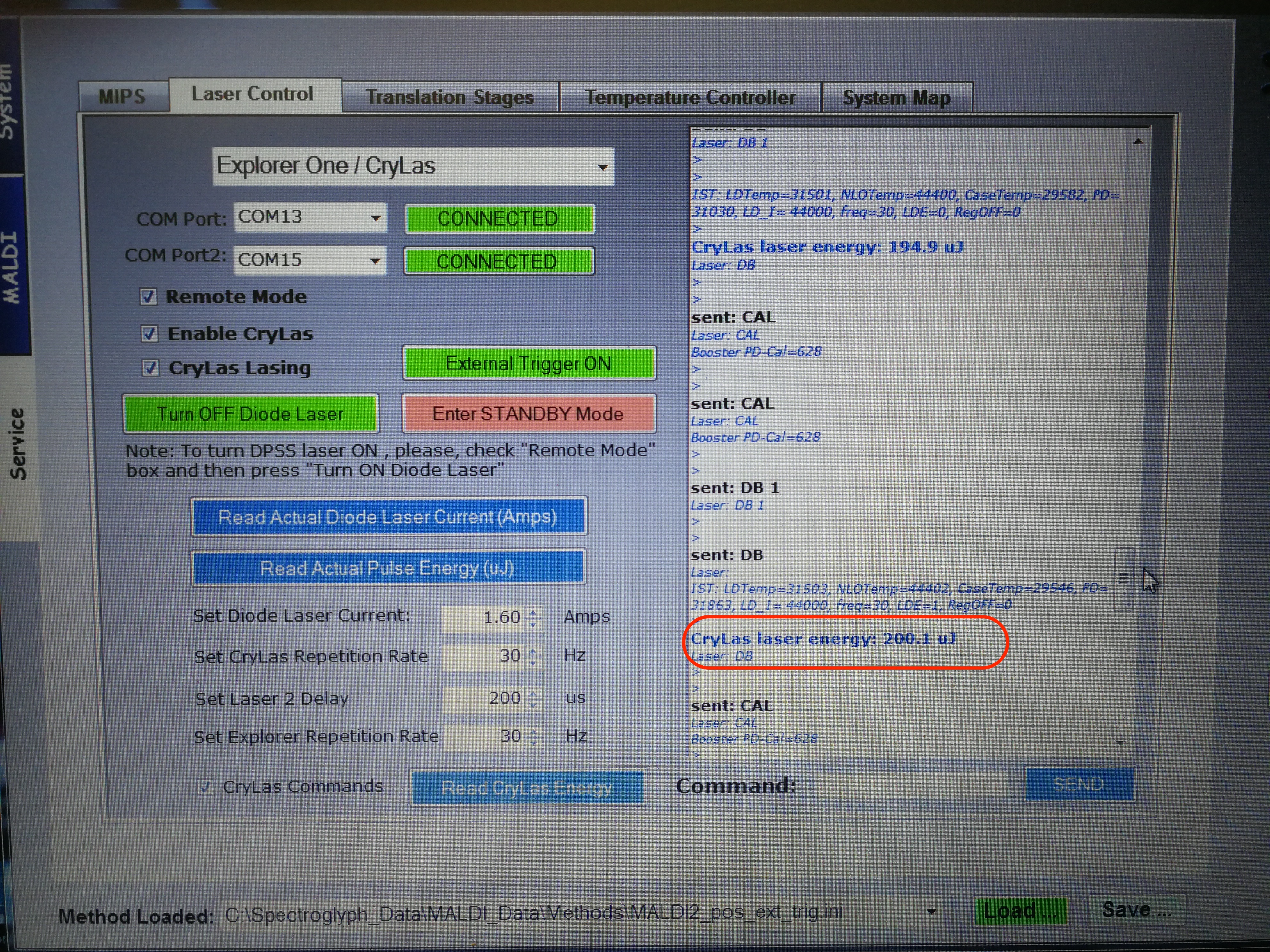
Figure 2.26: MALDI Laser Energy adjust.
Here is an example of good working Crylas condition.
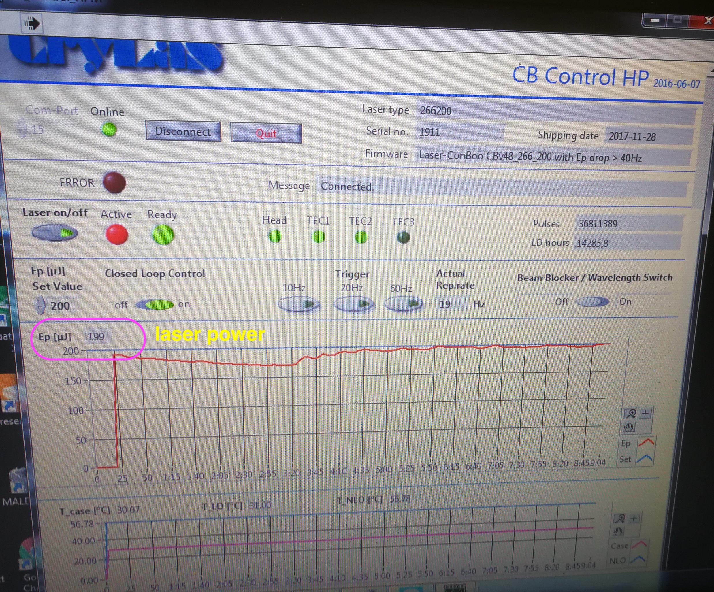
Figure 2.27: Laser power readour from CB Control HP software
To use the CB control HP software, you need to switch Crylas to internal trigger in Crylas controller. Then you need to connect and click laser on in the software in order to read the laser power and NLO temperature.
- Now you need to find MALDI2 ions. First, block Explorer one laser, and make sure you can see ions from Crylas laser (TIC about x 1^4(5)). Then you need to find ions which only appear when both lasers are on, i.e., such ions will disappear when either of the laser is off. Only when you observed such ions can you claim that ions are aligned.
2.3.6 Scan duration time inconsistency
Description: The scan duration time in MALDI position file is significantly different from the maximum injection time in Orbitrap tune file; In addition, when the orbitrap is switched to standby mode, it still acquires data for 10-20 s.
Solution: Reset Orbitrap. See Orbitrap user manual for details regarding Orbitrap reset. (This bug may have been solved by the update of the MALDI Injector software)
2.4 Calibration
2.4.1 The MS calibration failed for Ion Mass/Res.
Description: Cal. (narrow): ion peak (74.1) not found
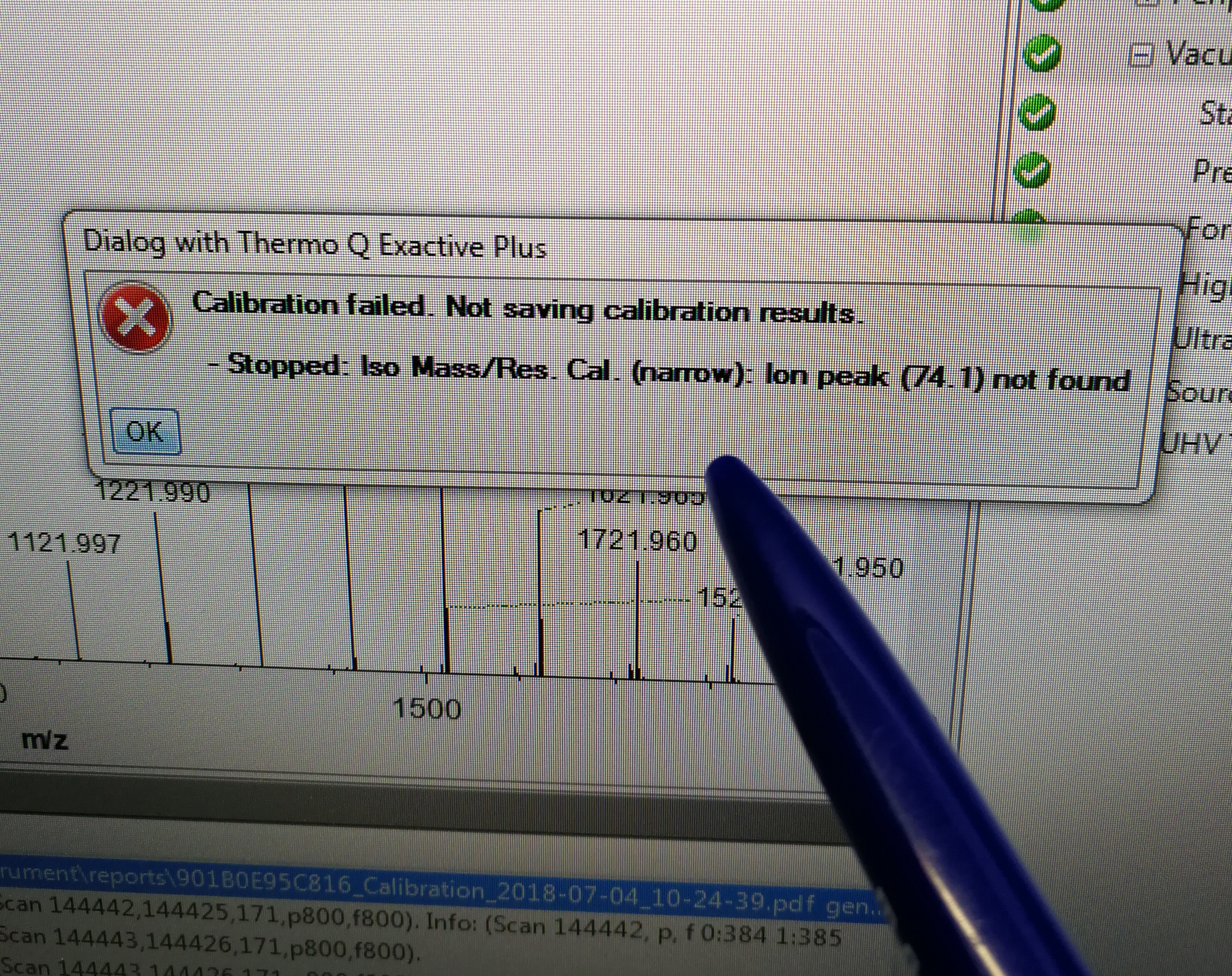
Figure 2.28: calibration error for Iso Mass/Res. Cal.(narrow)
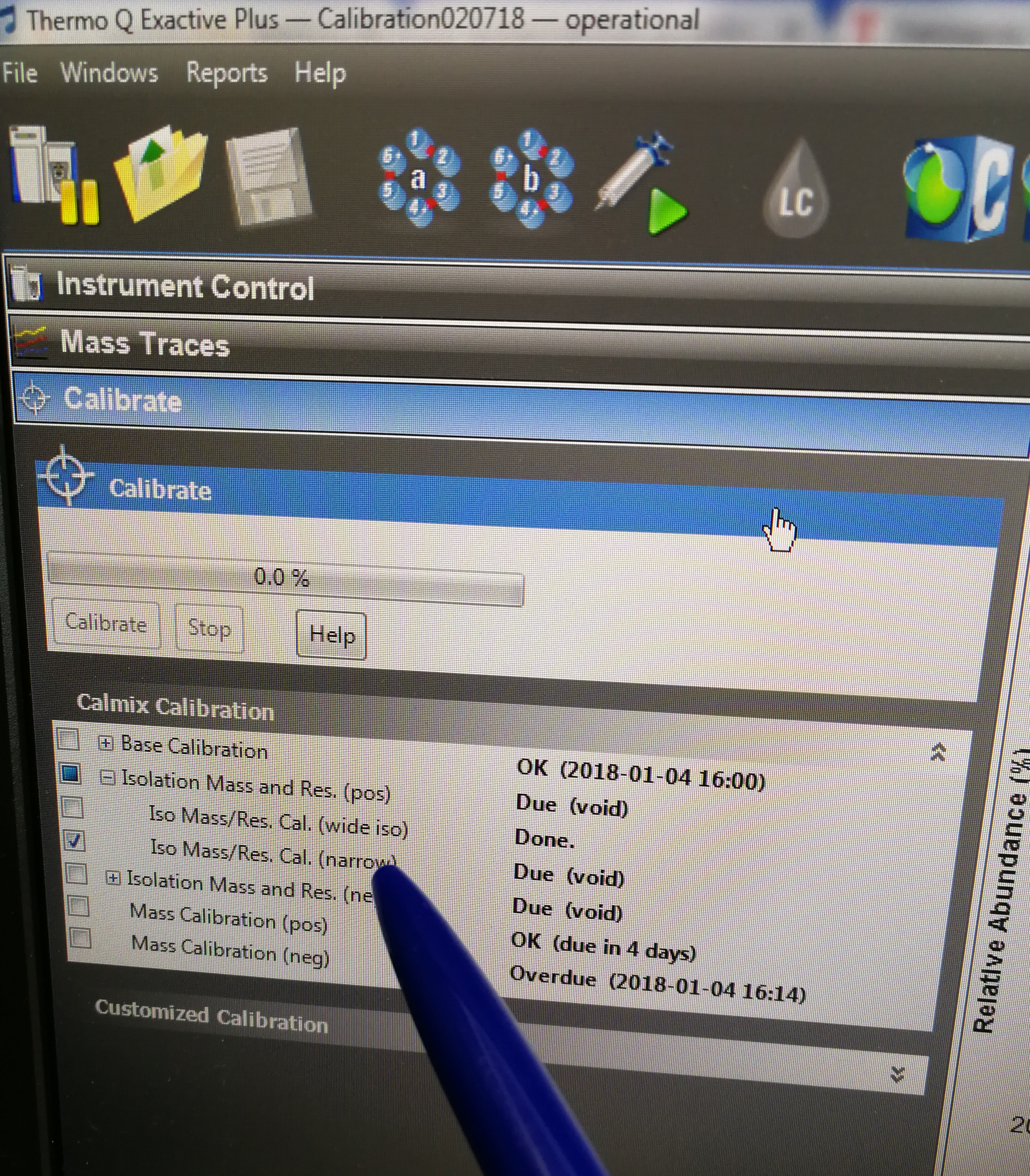
Figure 2.29: Iso Mass/Res. Cal.(narrow) tab
Solution:
- Observe the value for NL (normalized intensity level) and IT (injection time) in the spectrum window. As calibration solution infuses, and the read back values fluctuate, check the status of the ion current signal:
Is the signal present?
Is the signal stable? Check in the instrument status window that TIC variation has stabilized at about 15% or less from scan to scan.
- Before you run calibration, you must check if quadrupole isolates correctly. Any mass in the calmix.
References
Soltwisch, J., H. Kettling, S. Vens-Cappell, M. Wiegelmann, J. Muthing, and K. Dreisewerd. 2015. “Mass Spectrometry Imaging with Laser-Induced Postionization.” Science 348 (6231): 211–15. https://doi.org/10.1126/science.aaa1051.